
Articles
Introducing the SiTek SPC-PSD
When using a PSD there is usually the need for some analog signal processing of the PSD signals.
In order to facilitate this task, SiTek has designed an analog signal processing circuit (SPC) that converts the output photocurrents from the PSD to voltages. These bipolar voltages are processed and output as difference- and sum-signals and represent the position and intensity of the centroid of a light spot on the PSD.
The differential signal is directly proportional to the current difference
between the photocurrents from one electrode pair on the PSD and thus, for
constant light intensity, represents the position of the impinging light spot
between the electrodes. For a one-dimensional PSD there is only one differential
signal to keep track of. The two-dimensional detector has two electrode pairs
and hence there are two sets of differential signals.
If light intensity is not constant the differential signal will vary
proportional to the light intensity making it impossible to get the desired
position
information. The remedy is to divide the differential signal with a signal
proportional
to the intensity of the impinging light. Such a signal is the sum signal,
which is proportional to the sum of the photocurrents from an electrode
pair and
thus to the total photocurrents. As for the differential signal there
are one or two sets of sum signals – one for each electrode pair.
It may seem unnecessary to have two sets of sum signal for the two-dimensional
case
as
in theory both the two sets should equal the total photocurrent. But
in
many instances it is practical to have access to both the pairs of sum
signals
as they have opposite polarity. Also from an accuracy point of view it
is advantageous
to use the same currents as were used to form the difference signal to
form the sum signal. By doing this the influence of any deviations in
amplification in the different steps will be minimized.
The SiTek SPC uses FET current to voltage converters (transimpedance amplifiers)
that simply consists of just a FET op-amp and a feedback resistor of 100 k
ohms. Provisions are made for bias supply to the PSD by means of a resistor
and a voltage divider on the op-amp positive input that restores zero voltage
output for zero photocurrent input.
Field effect (FET) op amps are used because of their high input impedance,
low noise and small op-amp input currents.
All the outputs of the transimpedance amplifiers are available on the SPC pins.
The difference signals are formed in a couple of differential op-amps. The
all over amplification in these stages is set to 1. In order to satisfy the
most demanding applications, there is also an offset adjustment input for both
differential amplifiers.
The same goes for the two summation amplifiers where offset also can be adjusted. The sum signal (intensity signal) is intended for compensation of the position signal intensity dependence. This can be accomplished by dividing this signal by the intensity signal or by using the intensity information in a feedback loop for regulating the light source to give a constant illumination on the PSD.
The dynamic properties
of the SPC are excellent with a 400 kHz bandwidth and a slew rate of
13 V/µs.
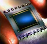
In order to obtain maximum precision, high reliability and small size the SPC
is built using thick film technology and laser trimmed resistors on a 20,5
x 20,5 mm2 ceramic substrate. The SPC is delivered with surface mount leads,
but these can upon request be changed for DIL leads.
Normally the SPC comes complete with a 2L10 or 2L4 PSD or any of our one-dimensional
PSDs. But of course, the signal processing circuit can also be used as a stand-alone
front-end together with any of our PSDs.