The PSD School
Section 1 by Lars Stenberg, ESDE AB
Why is the existence of position sensing detectors so important?
By optronics we mean an area of technology that are based on the simultaneous use of optics and electronics. Since optical elements such as lenses and prisms must always be fixed with the help of mechanical parts, often with a high degree of precision, optical instruments generally consist of precision-tooled parts. Optical instruments also often contain a computer. If we wish to develop, construct and manufacture optical instruments, we need knowledge of optics, electronics and precision tooling, and often knowledge of computer technology and programming.
In order to translate light into electrical signals, light-sensitive detectors that produce an electrical signal when exposed to light are needed. Up until the beginning of the 1970's, light-sensitive detectors were either bolometers, selenium cells, photocells, otomultipliers or photodiodes. However, in 1971 the so-called CCD array was invented at AT&T Bell Telephone Lab in the USA, and at about the same time the so-called PSD detector was invented by Chalmers engineers L.E. Lindholm and G. Petterson. The interesting thing about these detectors was that they were able to sense position, but we will return to that subject. The first microcomputer, the Intel 4004, was also constructed in 1971. As we will see further on, these inventions were important in themselves, but together they were so important for the possibility of constructing optronics products that if one wishes to determine a birth date for optronics, I know no better year than 1971.
Why are position sensing detectors so important?
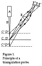
Let me give you an example of a simple measuring device which is used in the entire industrialised world in a number of different applications for automatic measurement and production control. We start by looking at Figure 1 to the right.
 A is
a source of light that sends out a small beam B, which strikes surface C at point D. If
surface C is not a mirror, the light will be subject to diffusion by reflection, that is,
the light will be reflected in all directions in a hemisphere around point D. The
intensity will vary somewhat in different directions depending on the properties of
surface C. If we place a lens or an objective E such that the lenses optical axis
intersects surface C at point D, all light passing through lens E will be more or less
well focused (depending on what kind of lens is used) at point F. The distance EF depends
on the distance DE and the lens's focal length.
A is
a source of light that sends out a small beam B, which strikes surface C at point D. If
surface C is not a mirror, the light will be subject to diffusion by reflection, that is,
the light will be reflected in all directions in a hemisphere around point D. The
intensity will vary somewhat in different directions depending on the properties of
surface C. If we place a lens or an objective E such that the lenses optical axis
intersects surface C at point D, all light passing through lens E will be more or less
well focused (depending on what kind of lens is used) at point F. The distance EF depends
on the distance DE and the lens's focal length.If surface C is moved up to a new position C´, light ray B will instead be diffusely reflected around point D´. Since lens E remains in its original position, the reflected light will now be focused somewhere along the extension of the line D´E. Using the so-called lens formula, that point can be calculated precisely1. In the figure the new position of the image is denoted with F. If the surface C is instead moved down to the new position C´´, by the same argument as above there will be a new image point F´´2. The alert reader will realise that when the surface is moved from C´ to C´´, the reflected and focused light's image point will move from F´ to F´´.In order to measure the movement of surface C by using the movement of image point F, one must have a position sensing detector that can be placed along the line F´F´´. This meant that before 1971 it was impossible to manufacture measuring instruments based on the so-called triangulation principle. As will be seen in the coming articles, for the same reason it is impossible to manufacture other kinds of measuring devices without access to position sensing detectors. These detectors are therefore necessary if optronical measurement and control devices are to be constructed.
The functional principle of a PSD
Now we look a little more closely at how position sensing detectors are function without, however, going into detail3. PSD is an abbreviation for Position Sensing Detector.
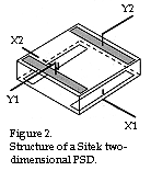
A PSD is essentially a photodiode that transforms light striking it to an electrical current. The component has two contacts placed directly across from each other on the active surface, see the Figure.
 For a two-dimensional PSD we also have a pair of
electrodes placed on the back side such that they are at a 90° angle to the electrode
pair on the front. The current that is generated will be divided between the two contacts
on each side (in one case because of electrons and in the other case because of holes).
The active surface functions as a very homogenous resistance, so that the current in each
contact depends linearly on where on the surface the light strikes, that is, the distance
to each contact. The position in the y direction is obtained through the simple formula
(Y1-Y2)/(Y1+Y2), where Y1 and Y2 are the currents from each contact. The position is
obtained similarly for the x direction. In other words, we can determine the light's
position in both x and y directions.
For a two-dimensional PSD we also have a pair of
electrodes placed on the back side such that they are at a 90° angle to the electrode
pair on the front. The current that is generated will be divided between the two contacts
on each side (in one case because of electrons and in the other case because of holes).
The active surface functions as a very homogenous resistance, so that the current in each
contact depends linearly on where on the surface the light strikes, that is, the distance
to each contact. The position in the y direction is obtained through the simple formula
(Y1-Y2)/(Y1+Y2), where Y1 and Y2 are the currents from each contact. The position is
obtained similarly for the x direction. In other words, we can determine the light's
position in both x and y directions.The principle above can also be used for constructing linear PSD detectors. In that case it is sufficient with one electrode on the silicon chips back side. It is even possible to make an almost circular PSD detector from a linear one by making the active upper surface in the form of an almost closed circle.
The functional principle of a CCD
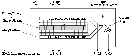
CCD stands for Charge Coupled Device. In order to understand how a CCD functions, we start by studying one-dimensional or linear CCD detectors, which have their light-sensitive elements or photodiodes arranged in a line as shown in Figure 3 above4. When the different photodiodes are struck by light, the light is transformed into electrical charges whose size is proportional to the intensity of light.

The generated charges are stored in an MOS capacitor, which is connected to each light-sensitive element. When the CCD array's light information is to be registered, the different charges are moved along the row of capacitors, just as in an analogue written register. When the charges are moved at the time of registration, they are transformed to a voltage that is directly proportional to the size of the charges, and thereby proportional to the intensity of light striking the detector. A CCD array can, in other words, be considered a "black box" that transformed a spatially distributed light to a signal voltage distributed in time.
Comparison between a PSD and a CCD5
If we now compare a PSD and a CCD, there are a number of differences that can be quite important to be aware of when choosing a type of detector for a certain application.
If we begin by looking at the resolution, it is possible to measure changes in position with a PSD as small as several nm (1:1 000 000), but for common applications a resolution of 1/2 000-1/4 000 of a PSD's linear extent are often used. A PSD with a photosensitive surface of 4 x 4 mm has then a resolution of 1-2 µm. A CCD, however, has a pixel size of 7 x 7 µm, and thus a resolution of 7 µm, since every photosensitive element is only separated from its neighbour by an extremely thin oxide layer. By recording the amount of light striking every pixel and calculating the intensity curve purely mathematically, the centre of the so-called "centre of gravity" for the light can be calculated in some cases. The resolution of a CCD can in such cases be increased to 0,5 µm. The sampling frequency may be 10 Mhz to 10 kHz for a PSD, depending on the size, as compared with 2 kHz for a linear CCD and 30 Hz for a CCD matrix6. The high sampling frequency achieved with a PSD is one of its key advantages.
If a PSD is struck by stray light with the same wavelength and signal frequency as the measurement ray itself, it will be difficult to deal with, since the x-y co-ordinates that the PSD presents depend on the common "centre of gravity" for the measurement ray and the stray light. As for the CCD array, it is possible to set a threshold level that serves to filter out signals weaker than the set level. In this way the error introduced by the stray light can be eliminated, given that the signal voltages caused by the stray light are less than those caused by the measurement ray.
And finally, looking at the cost of using a PSD or a CCD, it is possible to construct cheaper measuring systems using small PSD detectors than with either linear or matrix types of CCD.
What can a PSD be used for? Examples of applications.
In a series of coming articles we will discuss various applications in which position sensing detectors can be used. The next article will therefore discuss the choice of components and geometry that must be made when constructing a triangulation probe.
|
« home