The PSD School
Section 9 by Lars Stenberg, ESDE AB
What happens when a light beam hits a surface?
This section of the PSD school will examine, in more detail, the demands placed on the optics of the receiver where the intention is to develop a triangulation probe; for example, the light intensity and optical reproduction properties that this should possess. Before we can specify the receiver's exact optical characteristics we must, however, first study what happens with the collimated light beam when it hits the measurement surface; how the light is diffused when it is reflected as well as the demands it makes for the aperture of the receiver optics, and optical correction.
What happens when a light beam hits a surface?
When a light beam hits the interface of a medium, a certain amount of the light is reflected, a certain amount is transmitted through the medium and a certain amount is absorbed by the medium itself. If the reflection coefficient is designated by r, the transmission coefficient by t and the absorption coefficient by a it is evident that
r + t + a = 1
Using the geometry that I described in section 3 of the PSD school, we see that the reflection coefficient r must not be = 0 and also that the absorption coefficient a must not be almost equal to 1 (i.e. black rubber or velvet) because, in that case, very little light will be reflected in the direction of the receiver optics and the PSD. Which means thet we will have only a very small signal from the PSD detector. We can, therefore, see that it is a significantly easier task to design a triangulation probe for material whose absorption coefficient a approaches 0. It is also important to be careful with material whose transmission coefficient t > 0. If we have a material where
t > 0.5 (for example polished Plexiglas) it might happen that our collimated light beam could be reflected partly by the surface of the Plexiglas itself and partly - for example - by a small air bubble within the Plexiglas itself. This means that we can obtain reflected light both from the surface and from the air bubble which also means that the PSD detector receives light from two different directions. This means that we may get a measurement error due to the fact that t is too large.
Interfaces for which r > 0 applies
We shall now study in more detail interfaces for which r > 0 applies. When a light beam reaches the interface of a medium, macroscopic surface patterns influence how much light is distributed in different directions. Even polished glass surfaces have microscopic surface patterns that affect the distribution of light. The difference when light hits a slightly more uneven surface compared to a polished surface is that the light, in the forme case, is dispersed through multiple reflections in the surface structure whereas polished surfaces diffuse the light owing to diffraction. Diffraction arises when the surface pattern is of roughly the same size as the reflected light's wave length.
Generally speaking, it is a fact that an uneven surface will distribute reflected light more uniformly in space, compared to a polished surface that distributes light unevenly on account of more or less periodic patterns that are generated in connection with polishing. If the surface structure is random, then so-called speckles appear as a pattern of light spots that constantly move. Another reason for the light to be diffused when striking an interface is if the surface is contaminated or polluted by, for example, small particles. One example of this is when one looks through a dirty car windscreen against the light.
Different types of reflection
It is, of course, possible to work out how the light will be diffused on hitting a surface with a specific structure, but this is very complicated. Instead of getting entangled in endless calculations as to how different surface patterns disperse light we shall therefore split up the light diffusion from reflection on to a surface into three different qualitative components that offer a significantly simpler method of classifying light scattering from a surface. Each and every one of the three components is characterised by the geometric appearance of the light diffusion and it is this which interests us most when we try to design a triangulation probe. The three components are the specular reflection share, the Lambert reflection distribution share and the share represented by Gaussian reflection diffusion.
Specular reflection
Specular reflection is a reflection without diffusion and wholly follows the reflection law that say the angle of incidence is equivalent to the reflection angle. On the basis of the triangulation probe's geometry - which I dealt with in section 3 of the PSD school - we can see that it is not possible to measure the distance to an optical mirror surface with the aid of a triangulation probe geometry, since the collimated light then hits the mirror surface at right angles. Since it is a question of specular reflection the light will be reflected back in the same direction from which it comes and no light then falls on the PSD detector. From the above, it is clearly very difficult to design triangulation probes with the geometry described above if the share of specular reflection in the measurement surface is too dominant. On the other hand, it is possible to get a triangulation probe to function if the geometry is changed to what appears in figure 1.
 One
must, nevertheless, be aware that the measurement area is reduced considerably if a
geometry of this kind is used. On the other hand, it is possible to achieve a very high
level of accuracy.
Lambert reflection diffusion
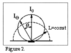
The Lambert reflection diffusion means that the luminance L (lm/steradian x m2) of the reflected light in the reflection point is constant for different angles Q, where Q is calculated from the surface's normal axis. In addition, for the light intensity I (lm/steradian) of the reflected light the following applies:

White paper, projection screens and roughly polished surfaces have a very large share of Lambert reflection dispersion. A Lambert reflector is thus characterised by the fact that the reflected light is visible under the solid angle < 2p steradians.
Gaussian reflection diffusion
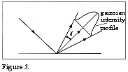
Gaussian reflection diffusion means that the reflected light follows the law of reflection but the reflected light forms a more or less thin beam centred around the reflection angle. The light intensity of Gaussian reflection diffusion has a Gaussian curve profile whose terminal points mark the double beam
 angle g. See
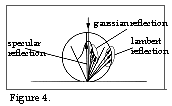
figure 3. If we now draw the three reflection components, where the angle of incidence i =
0, we obtain a figure with the following appearance:
From figure 4 it appears that the Lambert light dispersion is most important for the function of the triangulation probes since the beam angle g for the Gaussian light dispersion exceeds 25° by way of exception.
The light that is reflected against the measurement surface is often divided amongst the three reflection components above. It is possible to obtain a good idea of the distribution by directing, for example, a collimated laser beam against the measurement surface and visually observing how the light is dispersed. First, one observes if it is possible to see the luminous spot on the measuring surface even if the measuring surface is inclined in different directions. If it is possible to observe the measuring point clearly for different inclinations of the measuring surface this means that we have a significant share of Lambert light dispersion.
If we subsequently allow the collimated laser beam to strike the measuring surface under 45°'s angle of incidence, for example, and attempt to project the reflected light at 45 °'s reflection angle by placing a white paper at about 30 mm distance from the spot on the measuring surface struck by the laser beam, we can obtain an idea of the share of specular reflected light and the share of Gaussian light dispersion. See figure 5a.

If we obtain a point-formed light spot on the paper then this means a predominant share of specular reflection. See figure 5b. If we obtain a light spot where the light intensity is greatest in the middle and gradually diminishes (see figure 5c) then this signifies that there is a certain share of Gaussian light dispersion. If the light spot's diameter is, for example, 20 mm then this means that the beam angle g becomes atan(20/2x30) mm = 18.4 °. In this case, we can easily determine that the Gaussian component of the dispersed reflected light will not be able to pass through the receiver optics since the angle (according to section 3 of the PSD school) is 40° and the angle ß = 5.25°.
This means that the angle between the measuring surface's normal and the receiver optics optical axis will be (40-5.25)° = 34.75. The Gaussian reflection component will not therefore give rise to any light on the PSD detector.
The above example further underlines that the triangulation probes geometry means that the share of Lambert reflection diffusion must not be too small if the triangulation principle is to be able to function. The question of the proportion of Lambert reflection diffusion on a measuring surface is, in actual fact, the most important question to be answered when deciding if it is possible to use the triangulation principle for a certain measurement application.
In the next section of the PSD school I will attempt to describe how to choose the right lens type for the projection of the diffuse reflected light from the measuring point on the PSD detector.
|
« home