The PSD School
Section 13 by Lars Stenberg, ESDE AB
Further aspects of material selection
In chapter 12 we started to study the mechanical design of a triangulation probe with an examination of the most common metals and alloys that are used for the design of electro-optical instruments.
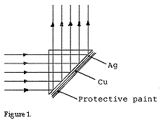
Copper is hardly used at all in the design of mechanical structures in optical instruments but is sometimes used as a cooling element on account of its high heat conductivity. On the other hand, copper is used as a corrosion protection in connection with different types of surface coatings. If - for example - one wishes to produce a reflective surface with a high reflection coefficient and to use silver, Ag, it is necessary to protect the silver surface against oxidation through the vaporization of a protective layer of Cu in a high vacuum chamber and subsequently painting the surface with a suitable paint (most frequently a 2-component paint) that does not let through damp.
See figure 1.
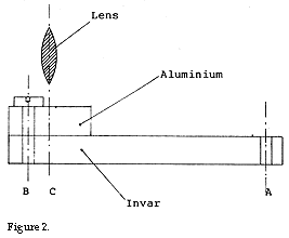
 Invar, which is an alloy of 64 % iron and 36 % nickel, is used in optical instruments on account of its low linear expansion in order to prevent different components moving in relation to each other when the temperature is changed. From table 1 in section 12 it appears that the coefficient of linear expansion for invar is 2 ppm compared with 10-12 ppm for iron and steel. A 100 mm long bar of invar increases its length by 100•50•2 ·10-6mm = 0.01 mm = 10 µm when its temperature increases 50°C compared with an equally long steel bar that increases its length by 100•50 11·10-6mm = 0.055 mm = = 55µm at a temperature change of the same amount. Sometimes the transfer that arises when one uses invar is too large and must therefore be reduced further. This may take place by making the invar bar longer than required and then screwing tight an aluminium bar at the outside end of the invar bar and subsequently screwing tight e.g. a lens holder in the end of the aluminium bar as shown in figure 2 below.
 When the temperature increases, the invar bar and thereby screw B moves to the left by 2 ppm per °C of the invar bar’s length between A and B. At the same time, the lens is moved to the right by 23.2 ppm per °C of the aluminium bar’s length between B and C. By this method it is possible to get components to retain their internal resistance within very tight tolerances across a large temperature range. If - despite everything - a small residual error were to be measured one can frequently enter this residual error as an error correction in an electronic memory. Through this example I wish to show that in certain cases it is possible to more or less wholly eliminate the effects of the linear expansion coefficient.
Iron and steel
Iron is never used in a pure form but always in the form of some alloy. Sometimes cast-iron is used when a more or less stable support is required. If one wishes to cast a stable support it is worth observing that there are special cast-iron alloys that dampen vibrations more effective than other cast-iron alloys.
The advantage of using cast-iron or steel when designing an optical instrument is that the linear expansion coefficient for cast-iron and steel (10-12 ppm) most frequently lies very near that for optical glass (8 - 10 ppm). This means that lenses that are mounted in cast-iron or steel holders are expanded or shrink as much as the holders when the temperature is changed. This in its turn means that stresses in the optical components do not arise that - in the worst case - may give rise to double refraction and thereby sharply deteriorated optical reproduction.
The disadvantages of using cast-iron or steel holders is that it is harder to provide such parts with an effective corrosion protection and internally with a matt black surface with low reflection in order to avoid scattered light. Parts of cast-iron or steel also become heavier and are harder to finish than e.g. aluminium which means that they become more expensive than aluminium parts.
What determines if one chooses steel or e.g. aluminium is where and how the instrument that is at the conceptual stage should be used. If one is to design a measuring instrument that is to be used within a large temperature range e.g. -40°C to +50°C and the instrument’s total precision depends on the geometrical distance between certain components (which applies to a triangulation probe) the choice inclines more towards cast-iron or steel than aluminium. If the instrument is more or less only to be used at room temperature then maybe aluminium is the right choice. If the instrument is included in a fixture that is to be brought into contact with a large number of parts every day then one should, perhaps, rather choose steel bearing in mind steel’s greater resistance to wear compared to aluminium, even if the measurements all the time take place at roughly the same temperature. In this case, it is possible - if so required - to also manufacture the most exposed surfaces in hard metals.
The reader may now ask perhaps if it is not possible to mix e.g. aluminium and steel in the same instrument. The answer is that it is possible but one must really watch out and think of what one is doing otherwise the effect may be the complete opposite to the example above where I mixed invar and aluminium. In a future chapter I will show what happens when materials are used with different linear expansion coefficients in an erroneous way in the same instrument.
Since there are so many different qualities of steel and cast-iron with very varied machining properties it is sensible to confer with an expert in the area rather than oneself attempts to find the right quality solely with the aid of brochures.
Magnesium is frequently used when the weight must be reduced as much as possible since the specific weight of magnesium is only just over half that of aluminium and 4-5 times less than that of steel. It is for this reason that magnesium and various magnesium alloys are frequently used within the aviation industry. A disadvantage with magnesium is that the finished parts must be protected against atmospheric attack through a special surface treatment that is called chromatisation and, in addition, most often they must be painted too. Another disadvantage is that magnesium and its alloys, which fall within the designation electron, easily catch fire on machining. Such a fire cannot be extinguished with water since water is decomposed by magnesium during hydrogen gas formation. The extinguishing takes place with cast-iron shavings or mineral oil with high viscosity and flash-point. If one wants to design mechanical parts in magnesium, it may therefore be wise to attempt to find a workshop that is interested in - and able to carry out - the machining of magnesium. Another disadvantage that magnesium shares with aluminium is the low surface hardness. This means that if one wishes to thread screw holes to be used from time to time then the threads should be reinforced with thread linings of steel. The above means that magnesium parts are more expensive than steel and aluminium ones. As a consequence, they are hardly something resorted to out of choice but rather are forced on one on account of external circumstances and demands.
Titanium has almost exactly the same magnitude of linear expansion coefficient (8.5 ppm) as optical glass and just over half the density and elasticity module of steel. Titanium does not corrode and is the only metal that is accepted by the body’s tissues without being expelled. The latter characteristic means that titanium is much used within the health care sector in order e.g. to fix prostheses in the body’s skeleton. On account of its strength, lightness and non-corrosive capacity titanium is used to a large extent within the aviation industry as well as submarine hulls. Titanium is about 50 times more expensive than steel.
Suitable applications for titanium are optical instruments that are used in fresh and/or salt water as well as for medical instruments that are to be used in bodily cavities or in connection with operations.
In the next chapter of the PSD school we shall conclude the discussion of different materials through studying certain selection criteria for optical glass as well as how the finished triangulation probe’s measurement precision is influenced by defective mechanical design solutions.
|
« home