The PSD School
Section 3 by Lars Stenberg, ESDE AB
Designing a triangulation probe
In section 2 of SiTek's PSD school, we looked at the design parameters for a triangulation probe and derived the 11 formulae which can be used to design a triangulation probe. In this chapter, we will use these formulae to make a more detailed study of the procedure for designing a triangulation probe. To make the reasoning clearer to the reader of section 3, we have inserted figures 2 and 3 from section 2 into this section.
Let us assume for our design example, that we need a free air distance of 100 mm from the lower edge of our proposed triangulation probe and measurement object D, and that the measurement range D'D" will be 45 mm. These two distances are of course determined by the measurement application in question. Since the lens is inside the triangulation probe and we may want to put a protective window in front to protect the main lens E, we will set h = 120 mm.
After this, we must decide the magnitude of angle ADF. As shown in figure 2, our first assumption is that the greatest measurement range D'D" is obtained by alt. 2.1 since the angle ADF is smallest. Let us use formula (2) from the PSD school section 2, to investigate the difference between the three cases. (Due to lack of space,the reader is requested to refer to section 2 of the PSD school for the other formulae 1-11.) According to formula 2,
we obtain the length of the measurement range D'D" for differing values of a and b to
In our table above, we find to our surprise that D'D" first falls when a increases from 30° to 45°, completely in accordance with our reasoning, but then increases as a increases from 45° to 60°. Why is this? The answer is obtained from the above formula 1, which specifies the distance from point D to the main lens E. The distance DE, which determines the measurement range together with angle b, quite simply increases faster than measurement range D'D" is reduced because angle a increases. In practice a angles greater than 35° to 45° are seldom used, so one seldom has to consider this fact in practice.
We have now found that if h is set to 120 mm and angle a is selected somewhere in the range of 30° to 45° and angle b is selected as 5°, we will obtain a triangulation probe of the required performance. Always attempt to keep angle b as small as possible since large b angles mean that main lens E will have large field angles and such lenses are always more expensive than lenses with small field angles. We will talk more about various types of lenses in future issues of SiTek's PSD school.
To calculate all the parameters in accordance with the above formulae 1-11 we need, finally, to set a value for the aperture fE of main lens E. If you have written a computer program, you can quite simply select fE = 20 mm for example and see what happens. After a couple of runs you have probably reached the specification you aimed at from the beginning. But it is not a bad idea to draw a scale illustration and use it to determine a value for EF (the distance between the lens and the image in the lens formula), which gives you a reasonably correct detector length. After this, you can use the lens formula to calculate a good start value for fE. If we study fig. 1, we see that a detector length of about 12 mm is required (note that the scale have been changed compared with the same figure in section 2), if b = 5°. If we want to use a detector of length 10 mm, we must use an EF value in the range of 41,5 mm. To be able to use the lens formula, we also need to know the distance DE (the distance from the object, which in this case is the diffusely reflected laser beam, to the main lens E). According to formula 1 for DE, we find that DE = 120/cos 40 = 156,65 mm. Putting these values into the lens formula (formula 6), gives fE = 32,81 mm.
Since we now have values for the four start parameters, we can now calculate the 11 above-mentioned formulae to find the total measurement range of the triangulation probe, the exact length of the detector and the angle g (angle between the detector plane and the optical axis of main lens E). For calculation 1, we thus use: h=120 mm, a=40°, b=5°, and fE = 32,81 mm.
The 11 expressions which must be calculated are numbered and the results are:
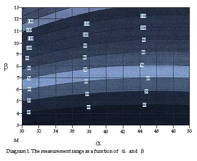
From (2) above, we see that the triangulation probe we are trying to design has a measurement range of 43,111 mm. The goal above was however that the measurement range should be 45 mm. There are two parameters we can change to increase the measurement range. We can either reduce angle a or increase angle b. Naturally, we can try several values of a and b to see what will happen. There is however another method which gives us a much better grasp, which is to use a calculation program such as Mathcad, and use it to plot a graph showing the correlation between a, b and measurement range D'D''. (See diagram 1.)
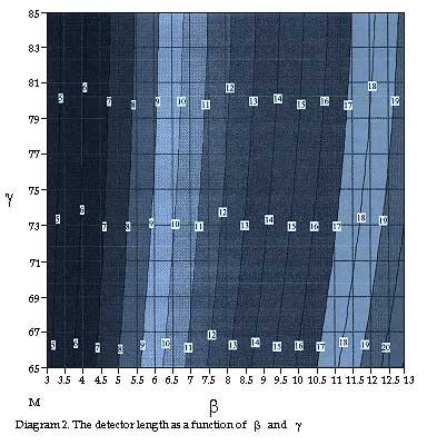
It can of course be suitable to plot a graph as well, showing the correlation between angles b, g and detector length F''F'. (See diagram 2.)
From diagram 1, we see that the measurement range is not affected so much if we change angle a as if we change angle b. Diagram 1 shows that if angle b is changed to 5,25°, the measurement range becomes 45 mm. For calculation 2, the values become h=120 mm, a=40°, b=5,25° and fE=32,81 mm. The result of calculation 2 is shown in the table above.
Since we increased angle b, this means that the detector length was increased from 7,621 mm to 8,005 mm. The logic of this is found by studying figure 3 above.
Assume that we want to use 8,25 mm of the detector length. (We will cover the reasons why we can not use the entire 10 mm length of the detector in section 4.) The best way for us to achieve this is by increasing the aperture of main lens E somewhat. A couple of iterations shows that if fE is chosen to be 33,5 mm, the desired result is obtained. For calculation 3, the values become h=120 mm, a=40°, b=5,25° and fE=33,50 mm. The result of the calculation is shown in the table above. We have therefore learnt in section 3 how to design a triangulation probe with the desired geometry by varying the four basic parameters. In section 4, I will cover how to select suitable optical parameters for the triangulation probe we are designing.
|
« home